Principle & Emf Equation of Transformer
Transformer is a device that is used to transfer electrical energy from one circuit to another using the phenomena of Mututal Induction. Keeping the energy conserved (it does not generate energy), it is used to increase or decrease voltage.
Working Principle
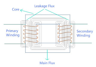
A basic transformer consists of two coils (or windings), one coil is connected to power supply. This power supply is alternating in nature (transformers don't work on dc). The alternating current passed through the coil generates flux which is also alternating in nature. Some part of this flux links with the second coil. As it is continuously changing, there must be a changing flux linkage in the second coil due to Mututal Induction. This changing flux in the second coil generates emf in the coil.
Primary Winding
The winding to which energy is supplied and generates flux to be transferred to second coil is called Primary Winding.
Secondary Winding
The winding in which emf is induced due to the flux transferred from the primary winding is called Secondary Winding. This gives us the desired output voltage.
However, this isn't how the transformers are built because a lot of flux does not get linked with the secondary winding and it gets wasted. In real transformer, this wastage of flux should be as minimum as possible, for that purpose core is used.
Core
The core provides a low reluctance path, through which maximum amount of flux generated by primary winding is passed and linked with the secondary winding.
So basically the transformer consists of 3 main parts: Primary Winding, Core and Secondary Winding.
Emf Equation
Let the primary winding of the transformer is connected to power supply. As a result of which flux \(\phi \) is generated in the primary winding. This flux is alternating in nature therefore, \[ \phi = \phi _m\sin{\omega t} \]
By Faraday's Law of Electromagnetic Induction and Lenz's Law:
\[ e = -N \frac{d\phi}{dt} \]
Emf induced at primary side:
\[ e_1 = N_1 \frac{d\phi}{dt} \]
where \(N_1\) is number of turns in primary winding
\[ \Rightarrow e_1 = -N_1\frac{d(\phi_m \sin{\omega t})}{dt} \]
\[ e_1 = -N_1\omega \phi_m \cos{\omega t} \]
\[ e_1 = N_1\omega \phi_m (-\cos{\omega t}) \]
\[ -\cos{\omega t} = \sin{(\theta - 90^o)} ,\hspace{20pt} \omega = 2\pi f \]
\[ e_1 = \phi_m 2\pi fN_1 \sin{(\omega t -90^o)} \]
Comparing with standard equation of emf
\[ e_1 = E_{m1}\sin{(\omega t + \psi)} \]
\[ E_{m1} = 2\pi f \phi_m N_1, \hspace{15pt} \psi = -90^o \]
RMS value of emf = \(\frac{E_{m1}}{\sqrt{2}} \)
\[ = \frac{2\pi f \phi_m N_1}{\sqrt{2}} \]
\[ \boxed{E_1 = 4.44 \phi_m f N_1 } \]
Similarly secondary side emf:
\[ \boxed{E_2 = 4.44 \phi_m f N_2 } \]
As \(\psi = -90^o \Rightarrow E_1 \text{ and } E_2 \) lag flux \(\phi \) by 90o
Phasor Diagram
Ratios in a Transformer
\[ E_1 = 4.44 \phi_m f N_1 \]
\[ E_2 = 4.44 \phi_m f N_2 \]
\[ \frac{E_1}{E_2} = \frac{4.44 \phi_m f N_1}{4.44 \phi_m f N_2} \]
\[ \boxed{\frac{E_1}{E_2} = \frac{N_1}{N_2} } \]
If we neglect resistance and leakage reactance
\[ E_1 \approx V_1 \text{ & } E_2 \approx V_2 \]
\[ \boxed{\frac{E_2}{E_1} = \frac{V_2}{V_1} = \frac{N_2}{N_1} = K \text{ (Turns ratio)} } \]
It is also called as Voltage Ratio
Primary side power = Secondary side power
\[ \Rightarrow V_1I_1 = V_2I_2 \]
\[ \frac{V_2}{V_1} = \frac{I_1}{I_2} \]
\[ \boxed{\frac{V_2}{V_1} = \frac{I_1}{I_2} = \frac{N_2}{N_1} = K } \]
It is called as current ratio
Step Up & Step Down Transformer
In Step Up Transformer, voltage on the secondary side is greater than voltage on the primary side \[ V_2 > V_1 \] \[ \Rightarrow K > 1 \] \[ \Rightarrow I_1 > I_2 \] In Step Down Transformer, voltage on the primary side is greater than voltage on the secondary side \[ V_1 > V_2 \] \[ \Rightarrow K \lt 1 \] \[ \Rightarrow I_2 > I_1 \]


