Ideal & Practical Transformer
Ideal Transformer
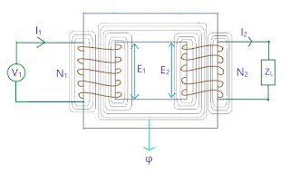
A ideal transformer is an imaginary transformer which has:
- -> no copper losses
- -> no iron loss in the core
- -> no leakage flux
More on losses Here
In ideal transformer, input power = output power. Concept of such transformer exists to make problems easier.
Characteristics of Ideal Transformer
Zero Winding Resistance : Resistance of both primary and secondary winding is 0 i.e. both the coils are purely inductive in nature.
100% Efficiency : There are no losses in ideal transformer so the input power = output power \(\Rightarrow E_1I_1 = E_2I_2 \)
No leakage flux : The whole amount of flux is linked from primary to secondary winding, so there is no leakage flux.
No Iron loss : As the iron core is subjected to alternating flux there occurs eddy current and hysteresis loss in it. These two losses together are called Iron loss. It is 0 in ideal transformer.
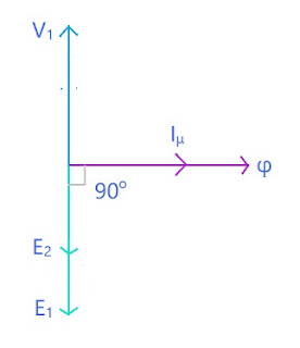
When an alternating voltage V1 is supplied to the primary winding of an ideal transformer, counter emf E1 is induced in the primary winding. Since there is no resistance, this induced emf E1 will be exactly equal to the applied voltage but in 180 degree opposite in phase.
The current drawn from the source produces required magnetic flux. As the primary winding resistance is 0, the current lags emf E1 by 90 degree. This is current is called Magnetizing current Iμ. This magnetizing current produces alternating magnetic flux φ. This flux gets linked with the secondary winding and emf E2 is induced by mutual induction. This E2 is in phase with E1. If the circuit is closed at secondary winding, then secondary current I2 is produced.
\[ E_1I_1 = E_2I_2 \]
Practical Transformer
In practical transformer, we have all sorts of losses that were 0 in ideal transformer like winding reistance, leakage flux, and iron losses, all are there.
Here we are gonna study two cases:
(a) No load
(b) On load
Practical Transformer on No Load
In no load transformer, the circuit on the secondary side is open.
V1 is the primary voltage and I1 is the primary current. Now I1 has two components:
a) One component is responsible for generation of magnetic flux. This is called Magnetizing component of I1 and is denoted by Iμ
b) Second component which is responsible for magnetic losses (Hysterisis and Eddy current losses) and primary winding losses. This is called Core loss component of Ic .
So its equivalent circuit diagram is:
where on primary side,
- V1 is Primary Voltage
- R1 is Primary Winding Resistance
- X1 is Primary Leakage Reactance
- I0 is No Load Primary Current
- Ic is Core Loss component of I1
- Iμ is Magnetizing Component of I1
- Rc is Core loss resistance
- Xm is Magnetizing Reactance
- N1 is Number of turns in Primary Winding
- E1 is Primary induced Emf
- R2 is Secondary winding resistance
- X2 is Secondary leakage reactance
- N2 is Secondary winding turns
- E2 is Secondary induced emf
- V2 is Secondary terminal voltage
On secondary side:
Phasor Diagram
Explanation
First we will start with reference line which is common to both primary and secondary curcuit, here it is flux φ. Now using KVL in primary circuit
\( V_1 = -E_1 + I_0R_1 + jI_0X_1 \)
There is no direct relation between φ and V1 so that we could directly draw phasor. But we have relation with E1 and φ, as φ is responsible for both E1
and E2. E1 and E2 both lag φ by 90 degrees. Here we will consider E1 < E2.
φ is produced due to magnetizing current Iμ therefore Iμ is in phase with φ. As we have -E1 in our equation (because it is in opposite direction of magnetizing current) so we will draw a phasor opposite to E1.
Ic is 90 degrees leading from Iμ so it is in phase with -E1
As I0 = Ic + Iμ , hence the phasor I0.
Now I0R1 is voltage drop in R1 and it is in phase with I0 , and as it is added to -E1 so the phasor of I0R1 will be drawn at the head of -E1. I0X1 is voltage drop across X1 and is 90 degrees leading I0R1, so it is drawn perpendicular to I0R1.
Now following the equation, V1 phasor is drawn adding all the quantities given in the equation.
Practical Transformer on Load
The secondary side is closed-circuited with a load.
Its equivalent circuit diagram:
where on primary side,
- V1 is Primary Voltage
- I1 is Primary Current
- I'2 is Primary Current to neutralize the demagnitizing effects of I2, I'2 = K I2
- I0 is No Load Primary Current
- R1 is Primary Winding Resistance
- X1 is Primary Leakage Reactance
- Ic is Core Loss component of I1
- Iμ is Magnetizing Component of I1
- I'1 component of I1 (doubtful)
- Rc is Core loss resistance
- Xm is Magnetizing Reactance
- N1 is Number of turns in Primary Winding
- E1 is Primary induced Emf
- R2 is Secondary winding resistance
- X2 is Secondary leakage reactance
- N2 is Secondary winding turns
- E2 is Secondary induced emf
- V2 is Secondary voltage
- I2 is Secondary current
On secondary side,
Phasor Diagram
Explanation
Again we will start with refrence line, here it is φ.
Using KVL in secondary circuit,
\( V_2 = E_2 - I_2R_2 - jI_2X_2 \)
As there is no direct relation between V1 and φ so we will use the equation to draw all three quantities and then add them to get V1.
E2 and E1 lag φ by 90 degrees. Here we will consider E2 <
E1. I2 lags E2 by phase difference of φ2
Now voltage drop I2R2 across R2 will be in phase with I2 but we need -I2R2 so we will it in opposite direction of I2.
As it is to be added to E2 so it will be drawn at the head of E2.
I2X2 is voltage drop across X2 and is leading by 90 degrees from I2R2. Again it is -ve in magnitude.
Adding all the quantities we have V2.
Now in primary circuit,
V1 = - E1 + I1R1 + jI1X1
I1 = I'2 + I0 where I'2 =
-KI2
I0 = Iμ + Ic
Again we will draw Iμ first as it is directly connected to φ, then Ic
and then I0 .
I'2 is opposite to I2 and is added to I0. The resultant phasor is I1.
I1R1 is in phase with I1 and is added to -E1.
I1X1 is 90 degrees leading I1R1.
Phase difference between V1 and I1 is φ1
Power Factor = cosφ1
Input Power = V1I1cosφ1
Phase difference between V2 and I2 is φ2
Power Factor = cosφ2
Input Power = V2I2cosφ2


