DC Generator
Principle of Operation
Basically, the principle of DC Generator is based on dynamically induced emf i.e. Faraday's Law of Electromagnetic Induction. This law states that :
"Whenever the magnetic flux linking with a conductor changes, an Electromagnetic Force (EMF) is set up in that conductor."
\[ \text{Dynamically induced emf }, e = \frac{d\phi}{dt} \]
The direction of flux is given by Right Hand Thumb Rule which states that "if the thumb of the right hand represents direction of current then direction of the curled fingers represent direction of flux".
Now the question arise, how do we change the flux? The answer is relative motion between the conductor and the flux. So there are two ways to do that:
1) Keep the conductor stationary and move the flux
2) Keep the flux stationary and move the conductor
In DC generator, we keep the flux stationary and move the conductor. The device that moves this conductor is called Prime Mover. Some examples of Prime Mover are: diesel engine, diesel turbine, steam turbine etc.
Now the next question arises, what is the direction of this induced emf? For that we have Fleming's Right Hand Rule:
"If the three fingers of right hand, namely thumb, index finger and middle finger are outstretched so that each one of them is at right angles with the remaining two and if in this position the index finger is made to point in the direction of flux, thumb in the direction of the relative motion of conductor w.r.t. flux then the outstretched middle finger gives the direction of induced emf in the conductor"
While in DC Motors, the rule used is Fleming's Left Hand Rule (not right hand rule).
The emf induced is alternating in nature. So the question arises: if the induced emf is alternating, how is it a DC Generator? The answer is a rectifier called as Commutator. This device is not electronic, instead its entirely mechanical.
"Commutator is a device used in DC Generator to convert alternating induced emf to unidirectional DC emf"
Construction
The construction remains same for both generator and motor.
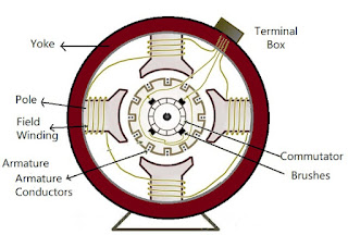
Yoke : It is the outermost protective cover of the machine. It protects all the components from dust, moisture etc. It serves as a mechanical support to the parts. It also provides low reluctance path for the flux, so its made up of Cast Iron as it is a magnetic material.
Pole : The pole has two parts:
Pole Core : It carries field windings which are responsible for production of magnetic flux.
Pole Shoe : It covers the maximum armature conductor to cut flux so that we have maximum induced emf.
As flux passes through it, it should provide a low reluctance path so it is made up of Cast Iron.
Field Winding : It is the coil or wire that carries the current which is responsible for the production of flux. It is made up of Copper.
Armature : That part where the emf is induced. It is made up of Cast Iron.
Armature Conductor : That part which takes the voltage or current out of armature to the commutator
Commutator : That part which rectifies AC emf to DC.
Brushes : It takes out the voltage or current from the Commutator to the terminals. It is made up of Carbon.
Emf Equation of DC Generator
Before we derive the emf equation, let's define some terms:
Let P = number of poles in the generator
φ = flux produced by each pole
N = speed of armature of generator (in rpm)
Z = total number of conductors in armature
A = number of parallel paths in which armature conductors are distributed
So by Faraday's Law of Electromagnetic Induction:
e = Rate of cutting of the flux
\[ e = \frac{d\phi}{dt} \]
Total flux = Flux produced by each pole × number of poles
So, total flux = φ × P
Time required to complete one revolution = 60/N
\[ e = \frac{\phi P}{\large\frac{60}{N}} \]
\[ e = \frac{\phi PN}{60} \]
This emf is for one conductor
As Z conductors are distributed in A parallel paths, effective number of conductors will be Z/A, so
\[ E = \frac{\phi PN}{60}\times\frac{Z}{A} \]
\[ \boxed{E = \frac{\phi PNZ}{60A} } \]
Types of Generators
On the basis of Excitation of field winding, there are two types of generators:
1) Seperately Excited Generator
2) Self Excited DC Generator
Seperately Excited Generator
A DC Generator whose field winding or coil is energised by a seperate or external DC source is called a seperately excited DC Generator.
Self Excited Generator
Self-excited generators are the generators which get excited with the initial current in the field coils.
What actually happens is: there is a small amount of magnetism present in the rotor iron. This residual magnetic field of the main poles, induces an emf in the stator coils, which produces initial current in the field windings.
Due to flow of small current in the coil, an increase in magnetic field occurs. As a result, voltage output increases,which in turn, increases the field current. This process continues as long as the emf in the armature is more than the voltage drop in the field winding. But after at certain level, field poles get saturated and at that point electric equilibrium is reached, and no further increase in armature emf and increase in current takes place.
Based on the connection of field winding to the armature, there are 3 types of generator
1) Series Generator
2) Shunt (Parallel) Generator
3) Compound Generator : Of 2 types
a) Long Shunt Compound Motor
b) Short Shunt Compound Motor
Series Wound Generator
In series wound generators, field winding and the armature winding are connected in series so that current that passes through external circuit and through field windings, passes from armature.
The field coil of series-wound generator has low resistance, and consists of a few turns of thick wire. If the load resistance decreases, then the current flow increases. As a result magnetic field and output voltage increases in the circuit. In such generators, output voltage varies directly with respect to load current which is not required in most of the applications. Due to this, it is not used a lot.
\[ I_{se} = I_a = I_L \]
Applying KVL we get,
\[ E_g - I_aR_A - I_{se}R_{se} - V_t = 0 \]
\[ E_g = V_t + I_aR_A + I_{se}R_{se} + V_{brush} \]
\[ \boxed{E_g = V_t + I_a(R_a + R_{se}) + V_{brush}} \]
where IaRa is Armature resistance drop, Eb is back emf and Vbrush is brush resistance drop
Shunt Wound DC Generators
In this type of generator, the field winding is wired parallel to the armature winding so that voltage is same across the circuit.
Here, field winding has many numbers of turns for the desired high resistance so that fewer armature current can pass through the field winding and the remaining passes through load.
In shunt wound generator, the output voltage is almost constant and if it varies then it varies inversely with respect to load current.
\[ I_a = I_{sh} + I_L \] \[ E_g - T_aR_a - V_t = 0 \] \[ \boxed{E_g = V_t + I_aR_a + V_{brush} } \] \[ \boxed{I_{sh} = \frac{V_t}{R_{sh}} = \frac{E_g - I_aR_a}{R_{sh}} } \]
Compound Generator
Compound Wound Generator is the best of both worlds i.e. series and shunt wound generators. On the basis of their connection they are of two types:
1) Long Shunt Compound Generator
2) Short Shunt Compound Generator
Long Shunt Compound Generator
The connection is made as shown in the diagram:
\[ I_{se} = I_a = I_{sh} = I_L \] \[ E_g = V_t + I_aR_a + I_{se}R_{se} + V_{brush} \] \[ = V_t + I_aR_a + I_{a}R_{se} + V_{brush} \] \[ \boxed{E_g = V_t + I_a(R_a + R_{se}) + V_{brush} } \] \[ \boxed{I_{sh} = \frac{V_t}{R_{sh}} = \frac{E_g - I_a(R_a + R_{se})}{R_{sh}} } \]
Short Shunt Compound Generator
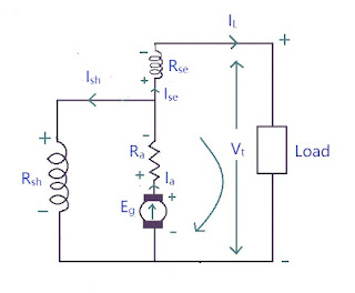
The connection is made as shown in the diagram:
\[ I_{se} = I_L \] \[ I_a = I_{sh} + I_{se} \] \[ E_g - I_aR_a - I_{se}R_{se} - V_t = 0 \] \[ \boxed{E_g = V_t + I_aR_a + I_{se}R_{se} + V_{brush} } \] \[ \boxed{I_{sh} = \frac{V_t}{R_{sh}} = \frac{E_g - I_aR_a - I_{se}R_{se}}{R_{sh}} } \]


