3 Phase Induction Motor
Construction
To understand its principle we need to know its construction.
It has mainly two parts:
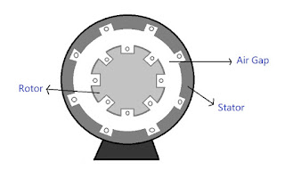
1) Stator
2) Rotor
Stator
It is the stationary part of the machine. It ha windings called Stator winding. 3-phase supply is provided to these windings. It also provides mechanical strength to the machine.
Rotor
It is a rotatory part of Induction motor. It has windings called Rotor winding. The conductors are placed on the periphery of the rotor.
On the basis of applications of Induction Motor they are of two types:
1) Slip Ring or Wound Rotor
2) Squirrel Cage Rotor
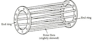
Squirrel Cage Rotor
Squirrel Cage Rotors are used where constant speed is required. In this type, both the end rings are permanently short-circuited. The conductors made up of Aluminium and Copper are placed between the end rings hence these are also short-circuited.
Hence the overall resistance of the rotor is constant and is used for the constant speed application. Example: Elevators.
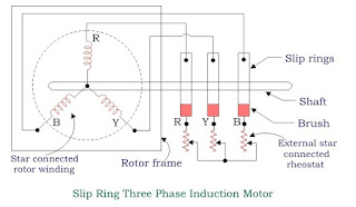
Slip Ring or Wound Rotor
This type of rotor construction is used where high starting torque is required.
In this type of rotor, Aluminium and Copper conductors are connected with the external Rheostat so that by varying resistance, the overall resistance of the rotor can be varied.
Working Principle
When 3 phase supply is given to the stator winding, a rotating magnetic field with speed called as Synchronous Speed (Ns) is generated. It rotates in clockwise direction.
As the magnetic field is rotating and the conductors are stationary, due to relative motion between magnetic flux and conductor, magnetic field gets cut and an emf is induced. Hence current starts flowing in rotor winidng.
Now as the conductors are current carrying and is placed in magnetic field, a torque is exerted on the rotor and the rotor starts to rotate in clockwise direction with a speed called as rotor speed.
Let's define some basic terms that we use with induction motor.
Slip Speed
It is the difference between Synchronous speed and rotor speed. \[ \text{Slip Speed } = N_S - N_R \]
Slip
It is defined as the ratio of Slip Speed to the Synchronous speed.
\[ S = \frac{N_S - N_R}{N_S} \]
1) When the motor is standing still
\[ N_R = 0 \Rightarrow \boxed{S = 1} \]
2) at NR = NS
\[ \boxed{S = 0} \]
Applications
Induction motor is used in fans, vaccum cleaners, washing machines, centrifugal pumps etc.


