Auto Transformer
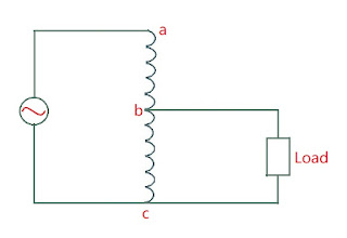
Auto Transformer is a transformer in which both primary and secondary side share same single winding i.e. one single winding is used as primary winding as well as secondary winding.
Here bc is called the common winding as it is shared by both primary and secondary sides. ab is called the series winding as it is in series with common winding.
Step Down Auto Transformer
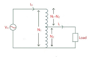
Here \( V_H =\) High Voltage
\( V_L =\) Low Voltage
\( I_H =\) High Voltage Current
\( I_L =\) Low Voltage Current
\( T_{ac} =\) number of turns across ac
\( T_H =\) number of turns across high voltage side \(= T_{ac} \)
\( T_{bc} =\) number of turns across bc
\( T_L =\) number of turns across low voltage side \(= T_{bc} \)
\(T_{ab} =\) number of turns across ab
\( T_{ab} = T_H - T_L \)
Also, \( I_H = I_{ab} \)
And when load is connected, \(I = I_{cb} \)
Now in auto transformer, we study two types of ratios: Circuit Voltage Ratio (CVR) and Winding Voltage Ratio (WVR).
CVR is the ratio of voltages in primary and secondary circuits
\[ CVR = \frac{V_H}{V_L} = \frac{T_H}{T_L} = a_A \Rightarrow \text{ Transformation Ratio } \longrightarrow (1) \]
WVR is the ratio voltages in the windings of the primary and secondary sides
\[ WVR = \frac{V_{ab}}{V_{bc}} = a \]
I flows only when load is connected and flows in opposite direction of IH. So the flux produced by I tries to reduce the flux produced by IH but the value of flux by IH is such that it nullifies the effect of flux by I. So the mmf by IH becomes equal to the mmf by I.
\[ I_{ab}T_{ab} = I_{bc}T_{bc} \]
\[ I_H(T_H - T_L) = IT_L \]
\[ \boxed{\frac{I}{I_H} = \frac{T_H - T_L}{T_L} = \frac{T_H}{T_L} - 1 = a_A - 1 } \longrightarrow (2) \]
WVR:
\[ a = \frac{V_{ab}}{V_{bc}} = \frac{T_{ab}}{T_{bc}} = \frac{T_H - T_L}{T_L} = \frac{T_H}{T_L} - 1 \]
\[ \boxed{a = a_A - 1 } \longrightarrow (3) \]
Applying KCL at point b
\[ I_H + I = I_L \]
\[ I = I_L - I_H \]
\[ \frac{I}{I_H} = \frac{I_L - I_H}{I_H} \longrightarrow (4) \]
From equation (2)
\[ a_A - 1 = \frac{I_L - I_H}{I_H} \]
\[ \boxed{a_A = \frac{I_L}{I_H} } \]
\[ \Rightarrow \boxed{a_A = \frac{V_H}{V_L} = \frac{T_H}{T_L} = \frac{I_L}{I_H}} \]
\[ \text{And } \boxed{a = a_A - 1} \]
Step Up Auto Transformer
All the calculations are same as in step down transformer, just the directions of currents change.
Saving in Conductor Material
As auto transformer uses single winding, it uses less matrial i.e. Copper in comparison to two winding transformers. To determine saving of Copper, we calculate weight of copper used.
Now the weight of copper used depends upon :
Current : because the flow of current depends upon the area of cross section of the turns of the winding. So larger the current means larger the area which in turn means more amount of Copper used
Number of Turns : larger the number of turns means more amount of Copper used.
For two winding transformer,
Weight of primary winding \( \propto N_1I_1 \)
Weight of secondary winding \( \propto N_2I_2 \)
Total Weight of Copper used \( \propto N_1I_1 + N_2I_2 \)
Weight of Copper in auto transformer \(\propto (N_1 - N_2)I_1 + N_2(I_2 - I_1) \)
\[ \frac{\text{Weight of Copper in auto transformer}}{\text{Weight of Copper in ordinary transformer}} \]
\[ = \frac{(N_1 - N_2)I_1 + N_2(I_2 - I_1)}{N_1I_1 + N_2I_2} \]
\[ = \frac{N_1I_1 - N_2I_1 + N_2I_2 - N_2I_1}{N_1I_1 + N_2I_2} \]
\[ = \frac{N_1I_1 - 2N_2I_1 + N_2I_2}{N_1I_1 + N_2I_2} \]
As \(N_1I_1 = N_2I_2 \)
\[ = \frac{2N_2I_2 - 2N_2I_1}{2N_2I_2} \]
\[ = 1 - \frac{I_1}{I_2} \]
\[ = \boxed{1 - K} \]
\[\Rightarrow \text{Weight of copper in ordinary transformer} = (1 - K)\times\text{Weight of copper in auto transformer} \]
So, Saving of Copper = Weight of copper in ordinary transformer - Weight of copper in auto transformer
\[ = W_0 - (1 - K)W_0 \]
\[ = W_0 - W_0 + KW_0 \]
\[ \boxed{\text{Saving of Copper } = KW_0} \]
When \(K \approx 1 \) saving is maximum
Advantages and Disdvantages
Due to single winding, it has lot of advantages when compared with 2 winding transformer and some disadvantages as well.
Advantages
a) In 2 winding transformer, transfer of energy occurs with the help of mutual induction only, but in auto transformer, due to single winding, energy transfer occurs through mutual induction as well as conduction of current.
b) Due to single winding, less material is used.
c) Due to single winding, leakage flux is very low.
d) Due to single winding, secondary winding resistance is very low.
e) It is of small size when compared to 2 winding transformer.
Disdvantages
a) If by mistake, the secondary side is open i.e. not connected to the winding, then all the high voltage will be transferred to the load, thus damaging the load.
b) Due to low impedance, an increase in short circuit current will damage the load.
Applications
a) In large power systems
b) In laborateries as variable transformer
c) Synchronous motor and induction motor are not self-starting, so it is used as a starter.


