DC Motor, Basic Electrical Engineering, Btech first year

DC Motor | Btech Shots!

DC Motor


Working Principle

The principle on which DC Motor works is:

"When a current carrying conductor is placed in a magnetic field, it experiences a mechanical force"

The construction of both DC Generator and Motor is same, the only difference is here we provide energy to the machine. As we excite the armature, the conductors of the armature, placed in magnetic field, experience a mechanical force and the motor starts moving. The direction of rotation is given by Fleming Left Hand Rule.

"Outstretch three fingers of left hand namely first finger, middle finger and thumb such that they are mutually perpendicular to each other. If we point first finger in direction of magnetic field and middle finger in direction of current, then the thumb gives direction of force experienced by the conductor."


Back EMF

Once motor starts rotating its conductor will cut magnetic flux produced by field winding, so by Faraday's Law of Electromagnetic Induction there will be induced emf just like in case of emf induced in dc generator. This emf is called Back emf. \[ \boxed{E_b = \frac{\phi PNZ}{60A} } \] The role of back emf in starting and running of the motor is important. The presence of back emf makes the DC Motor a self-regulating machine i.e. it makes the dc motor to draw as much armature current as is sufficient to develop the required load torque.

dc motor, dc machines, basic electrical engineering, btech first year

\[ V_t = I_aR_a + E_b + V_{brush} \] Vt is the supply voltage and it has to take care of all the three factors.


Torque Equation of DC Motor

      Mechanical Power = Torque × Angular Velocity
\[ P = T \times \omega \] \[ E_bI_a = T \times \frac{2\pi N}{60} \] \[ \frac{\cancel{N}P\phi Z}{\cancel{60}A} \times I_a = T \times \frac{2\pi \cancel{N}}{\cancel{60}} \] \[ \boxed{T = \frac{1}{2\pi}\phi I_a \frac{PZ}{A} } \] \[ \boxed{T = 0.159 \phi I_a \frac{PZ}{A} } \] The unit is Newton-meter (Nm).


Types of DC Motor

There are three types of motors:

1) Series Motor
2) Shunt Motor
3) Compound Motor : Of 2 types
      a) Long Shunt Compound Motor
      b) Short Shunt Compound Motor

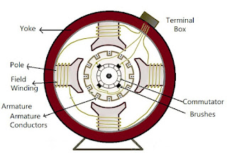
The construction of all these types are similar to dc generator.


DC Series Motor
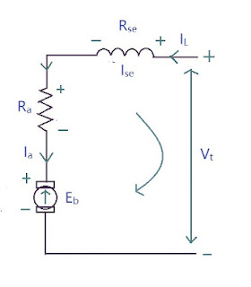
dc motor, dc machines, basic electrical engineering, btech first year

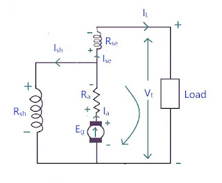
\[ I_L = I_{se} = I_a \] \[ E_b + I_aR_a + I_{se}R_{se} - V_t = 0 \] \[ E_b + I_aR_a + I_aR_{se} - V_t = 0 \] \[ E_b + I_a(R_a + R_{Se}) - V_t = 0 \] \[ \boxed{V_t = E_b + T_a(R_a + R_{se}) + V_{brush} } \]


DC Shunt Motor
dc motor, dc machines, basic electrical engineering, btech first year

\[ I_L = I_{sh} + I_a \] \[ E_b + I_aR_a - V_t = 0 \] \[ \boxed{V_t = E_b + I_aR_a } \] \[ \boxed{I_{sh} = \frac{V_t}{R_{sh}} = \frac{E_b + I_aR_a}{R_{sh}} } \]


Compound DC Motor
Long Shunt
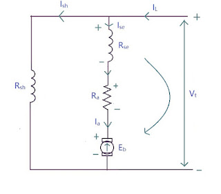
dc motor, dc machines, basic electrical engineering, btech first year

\[ I_L = I_{se} + I_{sh} \] Or \[ I_L = I_a + I_{sh} \] \[ E_b + I_aR_a + I_{se}R_{se} - V_t = 0 \] \[ \boxed{V_t = E_b + I_aR_a + I_{se}R_{se} } \] \[ \boxed{I_{sh} = \frac{V_t}{R_{sh}} = \frac{E_b + I_a(R_a + R_{se})}{R_{sh}} } \]


Short Shunt
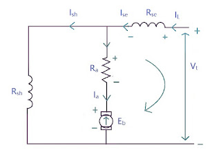
dc motor, dc machines, basic electrical engineering, btech first year

\[ I_L = I_{se} \] \[ I_L = I_{se} = I_a + I_{sh} \] \[ E_b + I_aR_a + I_{se}R_{se} - V_t = 0 \] \[ \boxed{V_t = E_b + I_aR_a + I_{se}R_{se} } \] \[ \boxed{I_{sh} = \frac{V_t}{R_{sh}} = \frac{E_b + I_aR_a + I_{se}R_{se}}{R_{sh}} } \]


DC Generator, Basic Electrical Engineering, Btech first year

DC Generator | Btech Shots!

DC Generator


Principle of Operation

Basically, the principle of DC Generator is based on dynamically induced emf i.e. Faraday's Law of Electromagnetic Induction. This law states that :

"Whenever the magnetic flux linking with a conductor changes, an Electromagnetic Force (EMF) is set up in that conductor."

\[ \text{Dynamically induced emf }, e = \frac{d\phi}{dt} \] The direction of flux is given by Right Hand Thumb Rule which states that "if the thumb of the right hand represents direction of current then direction of the curled fingers represent direction of flux".

Now the question arise, how do we change the flux? The answer is relative motion between the conductor and the flux. So there are two ways to do that:

1) Keep the conductor stationary and move the flux
2) Keep the flux stationary and move the conductor

In DC generator, we keep the flux stationary and move the conductor. The device that moves this conductor is called Prime Mover. Some examples of Prime Mover are: diesel engine, diesel turbine, steam turbine etc.

Now the next question arises, what is the direction of this induced emf? For that we have Fleming's Right Hand Rule:

"If the three fingers of right hand, namely thumb, index finger and middle finger are outstretched so that each one of them is at right angles with the remaining two and if in this position the index finger is made to point in the direction of flux, thumb in the direction of the relative motion of conductor w.r.t. flux then the outstretched middle finger gives the direction of induced emf in the conductor"

While in DC Motors, the rule used is Fleming's Left Hand Rule (not right hand rule).

The emf induced is alternating in nature. So the question arises: if the induced emf is alternating, how is it a DC Generator? The answer is a rectifier called as Commutator. This device is not electronic, instead its entirely mechanical.

"Commutator is a device used in DC Generator to convert alternating induced emf to unidirectional DC emf"

Construction

The construction remains same for both generator and motor.

dc generator, dc machines, basic electrical engineering, btech first year

Yoke : It is the outermost protective cover of the machine. It protects all the components from dust, moisture etc. It serves as a mechanical support to the parts. It also provides low reluctance path for the flux, so its made up of Cast Iron as it is a magnetic material.

Pole : The pole has two parts:

dc generator, dc machines, basic electrical engineering, btech first year

     Pole Core : It carries field windings which are responsible for production of magnetic flux.
     Pole Shoe : It covers the maximum armature conductor to cut flux so that we have maximum induced emf.
As flux passes through it, it should provide a low reluctance path so it is made up of Cast Iron.

Field Winding : It is the coil or wire that carries the current which is responsible for the production of flux. It is made up of Copper.

Armature : That part where the emf is induced. It is made up of Cast Iron.
  Armature Conductor : That part which takes the voltage or current out of armature to the commutator

Commutator : That part which rectifies AC emf to DC.

Brushes : It takes out the voltage or current from the Commutator to the terminals. It is made up of Carbon.


Emf Equation of DC Generator

Before we derive the emf equation, let's define some terms:
Let P = number of poles in the generator
φ = flux produced by each pole
N = speed of armature of generator (in rpm)
Z = total number of conductors in armature
A = number of parallel paths in which armature conductors are distributed
So by Faraday's Law of Electromagnetic Induction:
      e = Rate of cutting of the flux
\[ e = \frac{d\phi}{dt} \]     Total flux = Flux produced by each pole × number of poles
    So, total flux = φ × P
    Time required to complete one revolution = 60/N
\[ e = \frac{\phi P}{\large\frac{60}{N}} \] \[ e = \frac{\phi PN}{60} \] This emf is for one conductor
As Z conductors are distributed in A parallel paths, effective number of conductors will be Z/A, so \[ E = \frac{\phi PN}{60}\times\frac{Z}{A} \] \[ \boxed{E = \frac{\phi PNZ}{60A} } \]


Types of Generators

On the basis of Excitation of field winding, there are two types of generators:
1) Seperately Excited Generator
2) Self Excited DC Generator


Seperately Excited Generator

A DC Generator whose field winding or coil is energised by a seperate or external DC source is called a seperately excited DC Generator.

dc generator, dc machines, basic electrical engineering, btech first year
Self Excited Generator

Self-excited generators are the generators which get excited with the initial current in the field coils.

What actually happens is: there is a small amount of magnetism present in the rotor iron. This residual magnetic field of the main poles, induces an emf in the stator coils, which produces initial current in the field windings.

Due to flow of small current in the coil, an increase in magnetic field occurs. As a result, voltage output increases,which in turn, increases the field current. This process continues as long as the emf in the armature is more than the voltage drop in the field winding. But after at certain level, field poles get saturated and at that point electric equilibrium is reached, and no further increase in armature emf and increase in current takes place.

Based on the connection of field winding to the armature, there are 3 types of generator

1) Series Generator
2) Shunt (Parallel) Generator
3) Compound Generator : Of 2 types
      a) Long Shunt Compound Motor
      b) Short Shunt Compound Motor


Series Wound Generator

In series wound generators, field winding and the armature winding are connected in series so that current that passes through external circuit and through field windings, passes from armature.

The field coil of series-wound generator has low resistance, and consists of a few turns of thick wire. If the load resistance decreases, then the current flow increases. As a result magnetic field and output voltage increases in the circuit. In such generators, output voltage varies directly with respect to load current which is not required in most of the applications. Due to this, it is not used a lot.

dc generator, dc machines, basic electrical engineering, btech first year

\[ I_{se} = I_a = I_L \]
Applying KVL we get, \[ E_g - I_aR_A - I_{se}R_{se} - V_t = 0 \] \[ E_g = V_t + I_aR_A + I_{se}R_{se} + V_{brush} \] \[ \boxed{E_g = V_t + I_a(R_a + R_{se}) + V_{brush}} \] where IaRa is Armature resistance drop, Eb is back emf and Vbrush is brush resistance drop


Shunt Wound DC Generators

In this type of generator, the field winding is wired parallel to the armature winding so that voltage is same across the circuit.

Here, field winding has many numbers of turns for the desired high resistance so that fewer armature current can pass through the field winding and the remaining passes through load.

In shunt wound generator, the output voltage is almost constant and if it varies then it varies inversely with respect to load current.

dc generator, dc machines, basic electrical engineering, btech first year

\[ I_a = I_{sh} + I_L \] \[ E_g - T_aR_a - V_t = 0 \] \[ \boxed{E_g = V_t + I_aR_a + V_{brush} } \] \[ \boxed{I_{sh} = \frac{V_t}{R_{sh}} = \frac{E_g - I_aR_a}{R_{sh}} } \]


Compound Generator

Compound Wound Generator is the best of both worlds i.e. series and shunt wound generators. On the basis of their connection they are of two types:

1) Long Shunt Compound Generator
2) Short Shunt Compound Generator


Long Shunt Compound Generator

The connection is made as shown in the diagram:

dc generator, dc machines, basic electrical engineering, btech first year

\[ I_{se} = I_a = I_{sh} = I_L \] \[ E_g = V_t + I_aR_a + I_{se}R_{se} + V_{brush} \] \[ = V_t + I_aR_a + I_{a}R_{se} + V_{brush} \] \[ \boxed{E_g = V_t + I_a(R_a + R_{se}) + V_{brush} } \] \[ \boxed{I_{sh} = \frac{V_t}{R_{sh}} = \frac{E_g - I_a(R_a + R_{se})}{R_{sh}} } \]


Short Shunt Compound Generator

The connection is made as shown in the diagram:

dc generator, dc machines, basic electrical engineering, btech first year

\[ I_{se} = I_L \] \[ I_a = I_{sh} + I_{se} \] \[ E_g - I_aR_a - I_{se}R_{se} - V_t = 0 \] \[ \boxed{E_g = V_t + I_aR_a + I_{se}R_{se} + V_{brush} } \] \[ \boxed{I_{sh} = \frac{V_t}{R_{sh}} = \frac{E_g - I_aR_a - I_{se}R_{se}}{R_{sh}} } \]


3 Phase Induction Motor, Basic Electrical Engineering, Btech first year

3 Phase Induction Motor | Btech Shots!

3 Phase Induction Motor


Construction

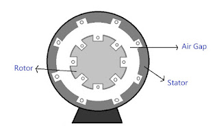
To understand its principle we need to know its construction. It has mainly two parts:

1) Stator
2) Rotor

3 phase induction motor, basic electrical engineering, btech first year
Stator

It is the stationary part of the machine. It ha windings called Stator winding. 3-phase supply is provided to these windings. It also provides mechanical strength to the machine.

Rotor

It is a rotatory part of Induction motor. It has windings called Rotor winding. The conductors are placed on the periphery of the rotor.


On the basis of applications of Induction Motor they are of two types:

1) Slip Ring or Wound Rotor
2) Squirrel Cage Rotor


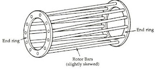
Squirrel Cage Rotor
3 phase induction motor, basic electrical engineering, btech first year

Squirrel Cage Rotors are used where constant speed is required. In this type, both the end rings are permanently short-circuited. The conductors made up of Aluminium and Copper are placed between the end rings hence these are also short-circuited.
Hence the overall resistance of the rotor is constant and is used for the constant speed application. Example: Elevators.


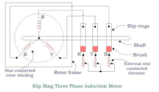
Slip Ring or Wound Rotor
3 phase induction motor, basic electrical engineering, btech first year

This type of rotor construction is used where high starting torque is required.
In this type of rotor, Aluminium and Copper conductors are connected with the external Rheostat so that by varying resistance, the overall resistance of the rotor can be varied.


Working Principle

When 3 phase supply is given to the stator winding, a rotating magnetic field with speed called as Synchronous Speed (Ns) is generated. It rotates in clockwise direction.

As the magnetic field is rotating and the conductors are stationary, due to relative motion between magnetic flux and conductor, magnetic field gets cut and an emf is induced. Hence current starts flowing in rotor winidng.

Now as the conductors are current carrying and is placed in magnetic field, a torque is exerted on the rotor and the rotor starts to rotate in clockwise direction with a speed called as rotor speed.


Let's define some basic terms that we use with induction motor.


Slip Speed

It is the difference between Synchronous speed and rotor speed. \[ \text{Slip Speed } = N_S - N_R \]

Slip

It is defined as the ratio of Slip Speed to the Synchronous speed. \[ S = \frac{N_S - N_R}{N_S} \]
1) When the motor is standing still \[ N_R = 0 \Rightarrow \boxed{S = 1} \] 2) at NR = NS \[ \boxed{S = 0} \]


Applications

Induction motor is used in fans, vaccum cleaners, washing machines, centrifugal pumps etc.


Electrical Machines, Basic Electrical Engineering, Btech first year

Electrical Machines | Btech Shots!

Electrical Machines


Topics that we are going to study in this unit:

Principle of Transformer & its emf equation, Basic Electrical Engineering, Btech first year

Principle & Emf Equation of Transformer | Btech Shots!

Principle & Emf Equation of Transformer


Transformer is a device that is used to transfer electrical energy from one circuit to another using the phenomena of Mututal Induction. Keeping the energy conserved (it does not generate energy), it is used to increase or decrease voltage.

Working Principle

A basic transformer consists of two coils (or windings), one coil is connected to power supply. This power supply is alternating in nature (transformers don't work on dc). The alternating current passed through the coil generates flux which is also alternating in nature. Some part of this flux links with the second coil. As it is continuously changing, there must be a changing flux linkage in the second coil due to Mututal Induction. This changing flux in the second coil generates emf in the coil.

Primary Winding

The winding to which energy is supplied and generates flux to be transferred to second coil is called Primary Winding.

Secondary Winding

The winding in which emf is induced due to the flux transferred from the primary winding is called Secondary Winding. This gives us the desired output voltage.

transformer, basic electrical engineering, btech first year

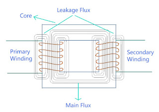
However, this isn't how the transformers are built because a lot of flux does not get linked with the secondary winding and it gets wasted. In real transformer, this wastage of flux should be as minimum as possible, for that purpose core is used.

Core

The core provides a low reluctance path, through which maximum amount of flux generated by primary winding is passed and linked with the secondary winding.


So basically the transformer consists of 3 main parts: Primary Winding, Core and Secondary Winding.

transformer, basic electrical engineering, btech first year

Emf Equation

Let the primary winding of the transformer is connected to power supply. As a result of which flux \(\phi \) is generated in the primary winding. This flux is alternating in nature therefore, \[ \phi = \phi _m\sin{\omega t} \]

transformer, basic electrical engineering, btech first year

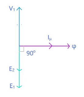
By Faraday's Law of Electromagnetic Induction and Lenz's Law: \[ e = -N \frac{d\phi}{dt} \] Emf induced at primary side: \[ e_1 = N_1 \frac{d\phi}{dt} \] where \(N_1\) is number of turns in primary winding \[ \Rightarrow e_1 = -N_1\frac{d(\phi_m \sin{\omega t})}{dt} \] \[ e_1 = -N_1\omega \phi_m \cos{\omega t} \] \[ e_1 = N_1\omega \phi_m (-\cos{\omega t}) \] \[ -\cos{\omega t} = \sin{(\theta - 90^o)} ,\hspace{20pt} \omega = 2\pi f \] \[ e_1 = \phi_m 2\pi fN_1 \sin{(\omega t -90^o)} \] Comparing with standard equation of emf \[ e_1 = E_{m1}\sin{(\omega t + \psi)} \] \[ E_{m1} = 2\pi f \phi_m N_1, \hspace{15pt} \psi = -90^o \] RMS value of emf = \(\frac{E_{m1}}{\sqrt{2}} \) \[ = \frac{2\pi f \phi_m N_1}{\sqrt{2}} \] \[ \boxed{E_1 = 4.44 \phi_m f N_1 } \] Similarly secondary side emf: \[ \boxed{E_2 = 4.44 \phi_m f N_2 } \] As \(\psi = -90^o \Rightarrow E_1 \text{ and } E_2 \) lag flux \(\phi \) by 90o

Phasor Diagram
transformer, basic electrical engineering, btech first year
Ratios in a Transformer

\[ E_1 = 4.44 \phi_m f N_1 \] \[ E_2 = 4.44 \phi_m f N_2 \] \[ \frac{E_1}{E_2} = \frac{4.44 \phi_m f N_1}{4.44 \phi_m f N_2} \] \[ \boxed{\frac{E_1}{E_2} = \frac{N_1}{N_2} } \] If we neglect resistance and leakage reactance \[ E_1 \approx V_1 \text{ & } E_2 \approx V_2 \] \[ \boxed{\frac{E_2}{E_1} = \frac{V_2}{V_1} = \frac{N_2}{N_1} = K \text{ (Turns ratio)} } \] It is also called as Voltage Ratio

Primary side power = Secondary side power \[ \Rightarrow V_1I_1 = V_2I_2 \] \[ \frac{V_2}{V_1} = \frac{I_1}{I_2} \] \[ \boxed{\frac{V_2}{V_1} = \frac{I_1}{I_2} = \frac{N_2}{N_1} = K } \] It is called as current ratio


Step Up & Step Down Transformer

In Step Up Transformer, voltage on the secondary side is greater than voltage on the primary side \[ V_2 > V_1 \] \[ \Rightarrow K > 1 \] \[ \Rightarrow I_1 > I_2 \] In Step Down Transformer, voltage on the primary side is greater than voltage on the secondary side \[ V_1 > V_2 \] \[ \Rightarrow K \lt 1 \] \[ \Rightarrow I_2 > I_1 \]


Losses & Efficiency in a Transformer, Basic Electrical Engineering, Btech first year

Losses & Efficiency in a Transformer | Btech Shots!

Losses & Efficiency in a Transformer


Losses in Transformer

Loss in any machine is when your output is lesser than the input you gave. In transformer this is loss is in terms of power. As it is a static device, there are only electrical losses in a transformer, unlike a motor which also has mechanical losses. All types of losses are:

(a) Core Losses or Iron Losses

Losses occuring in the core of the transformer. These are:

Hysteresis loss in transformer : Hysteresis loss occurs when there is reversal in the process of magnetization in the transformer core. This loss depends upon the volume and grade of the iron, value of flux density and frequency of magnetic reversals.

Eddy Current Loss in transformer : In transformer, AC current is supplied to the primary winding which sets up alternating magnetizing flux. When this flux links with secondary winding, it produces induced emf in it. But some part of this flux also gets linked with other conducting parts like steel core or iron body, which results in induced emf in those parts, resulting in small circulating currents in them. This current is called as Eddy current. Due to these eddy currents, some energy is dissipated in the form of heat causing Eddy current loss in transformer.

(b) Copper Loss

Copper loss occurs due to the resistance of the windings of the transformer. For primary winding, it is \(I_1^2R_1 \) and for secondary winding, it is \(I_2^2R_2\) where \(I_1 \) is primary current, \(R_1\) is primary winding resistance, \(I_2\) is secondary current and \(R_2\) is secondary winding resistance. As you can see, Copper loss is directly proportional to square of current and current depends on load, it implies that copper loss varies with the load connected to the transformer.


Efficiency of Transformer

Efficiency is given by ratio of output power to the input power.
Transformers are the most highly efficient electrical machines. Most of the transformers have full load efficiency between 95% to 98.5% .
As due to high efficiency, output is nearly equal to input power, so it becomes an impractical to measure efficiency using ratio of output and input. So a better way is to calculate the losses, subtract them from input and then calculate the ratio, \[ \text{Efficieny } = \frac{\text{Input - Losses}}{\text{Input}} \]

Condition for Maximum Efficiency

Input Power \( = V_1I_1\cos{\phi_1} \)
Let,
Copper Loss \( = I_1^2R_1 \)
Iron Loss \( = W_i\) \[ \text{Efficiency } = 1 - \frac{\text{Losses}}{\text{Input}} \] \[ \eta = 1 - \frac{I_1^2R_1 + + W_i}{V_1I_1\cos{\phi_1}} \] \[ \eta = 1 - \frac{I_1^2R_1}{V_1I_1\cos{\phi_1}} - \frac{W_i}{V_1I_1\cos{\phi_1}} \] Differentiating w.r.t. \(I_1\) \[ \frac{d\eta}{dI_1} = 0 - \frac{R_1}{V_1\cos{\phi_1}} + \frac{W_i}{V_1I_1^2\cos{\phi_1}} \] \(\eta\) will be maximum at \(\large\frac{d\eta}{dI_1} = 0 \)
So, \[ \frac{R_1}{V_1\cos{\phi_1}} = \frac{W_i}{V_1I_1^2\cos{\phi_1}} \] \[ \frac{I_1^2R_1}{V_1I_1^2\cos{\phi_1}} = \frac{W_i}{V_1I_1^2\cos{\phi_1}} \] \[ \boxed{I_1^2R_1 = W_i} \] Hence the efficiency of the transformer will be maximum when copper loss is equal to the iron loss.


Ideal & Practical Transformer, Basic Electrical Engineering, Btech first year

Ideal & Practical Transformer | Btech Shots!

Ideal & Practical Transformer


Ideal Transformer

A ideal transformer is an imaginary transformer which has:

  • -> no copper losses
  • -> no iron loss in the core
  • -> no leakage flux

More on losses Here
In ideal transformer, input power = output power. Concept of such transformer exists to make problems easier.


Characteristics of Ideal Transformer

Zero Winding Resistance : Resistance of both primary and secondary winding is 0 i.e. both the coils are purely inductive in nature.

100% Efficiency : There are no losses in ideal transformer so the input power = output power \(\Rightarrow E_1I_1 = E_2I_2 \)

No leakage flux : The whole amount of flux is linked from primary to secondary winding, so there is no leakage flux.

No Iron loss : As the iron core is subjected to alternating flux there occurs eddy current and hysteresis loss in it. These two losses together are called Iron loss. It is 0 in ideal transformer.

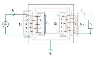
When an alternating voltage V1 is supplied to the primary winding of an ideal transformer, counter emf E1 is induced in the primary winding. Since there is no resistance, this induced emf E1 will be exactly equal to the applied voltage but in 180 degree opposite in phase.
The current drawn from the source produces required magnetic flux. As the primary winding resistance is 0, the current lags emf E1 by 90 degree. This is current is called Magnetizing current Iμ. This magnetizing current produces alternating magnetic flux φ. This flux gets linked with the secondary winding and emf E2 is induced by mutual induction. This E2 is in phase with E1. If the circuit is closed at secondary winding, then secondary current I2 is produced. \[ E_1I_1 = E_2I_2 \]

transformer, basic electrical engineering, btech first year

Practical Transformer

In practical transformer, we have all sorts of losses that were 0 in ideal transformer like winding reistance, leakage flux, and iron losses, all are there.
Here we are gonna study two cases:
(a) No load
(b) On load

Practical Transformer on No Load

In no load transformer, the circuit on the secondary side is open.

no load transformer, basic electrical engineering, btech first year

V1 is the primary voltage and I1 is the primary current. Now I1 has two components:
a) One component is responsible for generation of magnetic flux. This is called Magnetizing component of I1 and is denoted by Iμ
b) Second component which is responsible for magnetic losses (Hysterisis and Eddy current losses) and primary winding losses. This is called Core loss component of Ic .
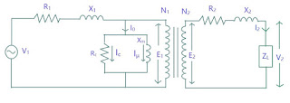
So its equivalent circuit diagram is:

no load transformer, basic electrical engineering, btech first year


where on primary side,

  • V1 is Primary Voltage
  • R1 is Primary Winding Resistance
  • X1 is Primary Leakage Reactance
  • I0 is No Load Primary Current
  • Ic is Core Loss component of I1
  • Iμ is Magnetizing Component of I1
  • Rc is Core loss resistance
  • Xm is Magnetizing Reactance
  • N1 is Number of turns in Primary Winding
  • E1 is Primary induced Emf

  • On secondary side:
  • R2 is Secondary winding resistance
  • X2 is Secondary leakage reactance
  • N2 is Secondary winding turns
  • E2 is Secondary induced emf
  • V2 is Secondary terminal voltage


Phasor Diagram
no load transformer, basic electrical engineering, btech first year
Explanation

First we will start with reference line which is common to both primary and secondary curcuit, here it is flux φ. Now using KVL in primary circuit
\( V_1 = -E_1 + I_0R_1 + jI_0X_1 \)
There is no direct relation between φ and V1 so that we could directly draw phasor. But we have relation with E1 and φ, as φ is responsible for both E1 and E2. E1 and E2 both lag φ by 90 degrees. Here we will consider E1 < E2.
φ is produced due to magnetizing current Iμ therefore Iμ is in phase with φ. As we have -E1 in our equation (because it is in opposite direction of magnetizing current) so we will draw a phasor opposite to E1.
Ic is 90 degrees leading from Iμ so it is in phase with -E1 As I0 = Ic + Iμ , hence the phasor I0.
Now I0R1 is voltage drop in R1 and it is in phase with I0 , and as it is added to -E1 so the phasor of I0R1 will be drawn at the head of -E1. I0X1 is voltage drop across X1 and is 90 degrees leading I0R1, so it is drawn perpendicular to I0R1.
Now following the equation, V1 phasor is drawn adding all the quantities given in the equation.


Practical Transformer on Load

The secondary side is closed-circuited with a load.

practical transformer, transformer on load, basic electrical engineering, btech first year

Its equivalent circuit diagram:

practical transformer, transformer on load, basic electrical engineering, btech first year

where on primary side,

  • V1 is Primary Voltage
  • I1 is Primary Current
  • I'2 is Primary Current to neutralize the demagnitizing effects of I2, I'2 = K I2
  • I0 is No Load Primary Current
  • R1 is Primary Winding Resistance
  • X1 is Primary Leakage Reactance
  • Ic is Core Loss component of I1
  • Iμ is Magnetizing Component of I1
  • I'1 component of I1 (doubtful)
  • Rc is Core loss resistance
  • Xm is Magnetizing Reactance
  • N1 is Number of turns in Primary Winding
  • E1 is Primary induced Emf

  • On secondary side,
  • R2 is Secondary winding resistance
  • X2 is Secondary leakage reactance
  • N2 is Secondary winding turns
  • E2 is Secondary induced emf
  • V2 is Secondary voltage
  • I2 is Secondary current

Phasor Diagram
transformer on load, practical transformer, basic electrical engineering, btech first year
Explanation

Again we will start with refrence line, here it is φ.
Using KVL in secondary circuit,
\( V_2 = E_2 - I_2R_2 - jI_2X_2 \)
As there is no direct relation between V1 and φ so we will use the equation to draw all three quantities and then add them to get V1.
E2 and E1 lag φ by 90 degrees. Here we will consider E2 < E1. I2 lags E2 by phase difference of φ2
Now voltage drop I2R2 across R2 will be in phase with I2 but we need -I2R2 so we will it in opposite direction of I2. As it is to be added to E2 so it will be drawn at the head of E2.
I2X2 is voltage drop across X2 and is leading by 90 degrees from I2R2. Again it is -ve in magnitude.
Adding all the quantities we have V2.
Now in primary circuit,
V1 = - E1 + I1R1 + jI1X1
I1 = I'2 + I0 where I'2 = -KI2
I0 = Iμ + Ic
Again we will draw Iμ first as it is directly connected to φ, then Ic and then I0 .
I'2 is opposite to I2 and is added to I0. The resultant phasor is I1.
I1R1 is in phase with I1 and is added to -E1. I1X1 is 90 degrees leading I1R1.
Phase difference between V1 and I1 is φ1
Power Factor = cosφ1
Input Power = V1I1cosφ1

Phase difference between V2 and I2 is φ2
Power Factor = cosφ2
Input Power = V2I2cosφ2


Equivalent Circuit of Transformer, Basic Electrical Engineering, Btech first year

Equivalent Circuit of Transformer | Btech Shots!

Equivalent Circuit of Transformer


The concept of Equivalent Circuits exists to help us analyze transformer as by using this concept, we can transform all the parameters to either side. When referred to primary side, it is called Equivalent Circuit referred to primary side and when referred to secondary side, it is called Equivalent Circuit referred to secondary side.

transformer, basic electrical engineering, btech first year

Here \( I_1 = I_0 + I'_2 \)
The no load primary current \(I_0\) is very small in comparison to full load current around 2% to 5% of full load current. So, \[ I_1 \approx I'_2 \] So we will interchange the core loss and leakage flux loss part with the winding losses part as shown in the diagram. This is called Approximate Equivalent Circuit.

transformer, basic electrical engineering, btech first year

The core losses and flux losses are negligible, so we will remove them to further simply the circuit,

transformer, basic electrical engineering, btech first year

Now we can perform calculations:

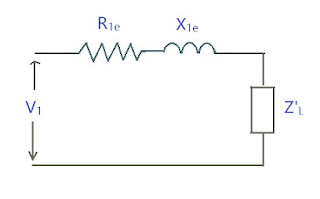
Equivalent Circuit referred to Primary Side

This means shifting all the elements to the primary side.

transformer, basic electrical engineering, btech first year

\(R_{1e} \) is Equivalent resistance referred to primary
\(X_{1e} \) is Equivalent reactance referred to primary
Before we get into equations for equivalent resistance and reactance, get this formula for relation between resistance and turn ratio: \[ V_1 = I_1R_1 , V_2 = I_2R_2\] \[ \frac{V_1}{V_2} = \frac{I_1R_1}{I_2R_2} \] \[ \frac{R_1}{R_2} = \frac{V_1I_2}{V_2I_1} = \frac{N_1}{N_2}\frac{N_1}{N_2} \] \[ \frac{R_1}{R_2} = \left(\frac{N_1}{N_2} \right)^2 \] So if \(R_2\) is to be referred from secondary to primary side, then it will be written as \[ R_2\left(\frac{N_1}{N_2}\right)^2 \] And if \(R_1\) is to be referred from primary to secondary side, then it will be written as \[ R_1\left(\frac{N_2}{N_1}\right)^2 \] So writing equations for equivalent resistance and reactance, \[ R_{1e} = R_1 + R_2\left(\frac{N_1}{N_2} \right)^2 \] \[ X_{1e} = X_1 + X_2\left(\frac{N_1}{N_2} \right)^2 \]

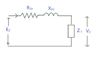
Equivalent Circuit referred to Secondary Side

This means shifting all the elements to the secondary side.

transformer, basic electrical engineering, btech first year

\(R_{2e} \) is Equivalent resistance referred to secondary
\(X_{2e} \) is Equivalent reactance referred to secondary
\[ R_{2e} = R_2 + R_1\left(\frac{N_2}{N_1} \right)^2 \] \[ X_{2e} = X_2 + X_1\left(\frac{N_2}{N_1} \right)^2 \]


Auto Transformer, Basic Electrical Engineering, Btech first year

Auto Transformer | Btech Shots!

Auto Transformer


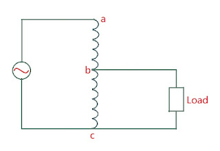
Auto Transformer is a transformer in which both primary and secondary side share same single winding i.e. one single winding is used as primary winding as well as secondary winding.

auto transformer, basic electrical engineering, btech first year

Here bc is called the common winding as it is shared by both primary and secondary sides. ab is called the series winding as it is in series with common winding.

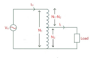
Step Down Auto Transformer
auto transformer, basic electrical engineering, btech first year

Here \( V_H =\) High Voltage
\( V_L =\) Low Voltage
\( I_H =\) High Voltage Current
\( I_L =\) Low Voltage Current
\( T_{ac} =\) number of turns across ac
\( T_H =\) number of turns across high voltage side \(= T_{ac} \)
\( T_{bc} =\) number of turns across bc
\( T_L =\) number of turns across low voltage side \(= T_{bc} \)
\(T_{ab} =\) number of turns across ab
\( T_{ab} = T_H - T_L \) Also, \( I_H = I_{ab} \)
And when load is connected, \(I = I_{cb} \) Now in auto transformer, we study two types of ratios: Circuit Voltage Ratio (CVR) and Winding Voltage Ratio (WVR).
CVR is the ratio of voltages in primary and secondary circuits \[ CVR = \frac{V_H}{V_L} = \frac{T_H}{T_L} = a_A \Rightarrow \text{ Transformation Ratio } \longrightarrow (1) \] WVR is the ratio voltages in the windings of the primary and secondary sides \[ WVR = \frac{V_{ab}}{V_{bc}} = a \] I flows only when load is connected and flows in opposite direction of IH. So the flux produced by I tries to reduce the flux produced by IH but the value of flux by IH is such that it nullifies the effect of flux by I. So the mmf by IH becomes equal to the mmf by I. \[ I_{ab}T_{ab} = I_{bc}T_{bc} \] \[ I_H(T_H - T_L) = IT_L \] \[ \boxed{\frac{I}{I_H} = \frac{T_H - T_L}{T_L} = \frac{T_H}{T_L} - 1 = a_A - 1 } \longrightarrow (2) \] WVR: \[ a = \frac{V_{ab}}{V_{bc}} = \frac{T_{ab}}{T_{bc}} = \frac{T_H - T_L}{T_L} = \frac{T_H}{T_L} - 1 \] \[ \boxed{a = a_A - 1 } \longrightarrow (3) \] Applying KCL at point b \[ I_H + I = I_L \] \[ I = I_L - I_H \] \[ \frac{I}{I_H} = \frac{I_L - I_H}{I_H} \longrightarrow (4) \] From equation (2) \[ a_A - 1 = \frac{I_L - I_H}{I_H} \] \[ \boxed{a_A = \frac{I_L}{I_H} } \] \[ \Rightarrow \boxed{a_A = \frac{V_H}{V_L} = \frac{T_H}{T_L} = \frac{I_L}{I_H}} \] \[ \text{And } \boxed{a = a_A - 1} \]

Step Up Auto Transformer
auto transformer, basic electrical engineering, btech first year

All the calculations are same as in step down transformer, just the directions of currents change.


Saving in Conductor Material

As auto transformer uses single winding, it uses less matrial i.e. Copper in comparison to two winding transformers. To determine saving of Copper, we calculate weight of copper used.

Now the weight of copper used depends upon :

Current : because the flow of current depends upon the area of cross section of the turns of the winding. So larger the current means larger the area which in turn means more amount of Copper used

Number of Turns : larger the number of turns means more amount of Copper used.

auto transformer, basic electrical engineering, btech first year

For two winding transformer,
Weight of primary winding \( \propto N_1I_1 \)
Weight of secondary winding \( \propto N_2I_2 \)
Total Weight of Copper used \( \propto N_1I_1 + N_2I_2 \)
Weight of Copper in auto transformer \(\propto (N_1 - N_2)I_1 + N_2(I_2 - I_1) \) \[ \frac{\text{Weight of Copper in auto transformer}}{\text{Weight of Copper in ordinary transformer}} \] \[ = \frac{(N_1 - N_2)I_1 + N_2(I_2 - I_1)}{N_1I_1 + N_2I_2} \] \[ = \frac{N_1I_1 - N_2I_1 + N_2I_2 - N_2I_1}{N_1I_1 + N_2I_2} \] \[ = \frac{N_1I_1 - 2N_2I_1 + N_2I_2}{N_1I_1 + N_2I_2} \] As \(N_1I_1 = N_2I_2 \) \[ = \frac{2N_2I_2 - 2N_2I_1}{2N_2I_2} \] \[ = 1 - \frac{I_1}{I_2} \] \[ = \boxed{1 - K} \] \[\Rightarrow \text{Weight of copper in ordinary transformer} = (1 - K)\times\text{Weight of copper in auto transformer} \] So, Saving of Copper = Weight of copper in ordinary transformer - Weight of copper in auto transformer \[ = W_0 - (1 - K)W_0 \] \[ = W_0 - W_0 + KW_0 \] \[ \boxed{\text{Saving of Copper } = KW_0} \] When \(K \approx 1 \) saving is maximum


Advantages and Disdvantages

Due to single winding, it has lot of advantages when compared with 2 winding transformer and some disadvantages as well.

Advantages

a) In 2 winding transformer, transfer of energy occurs with the help of mutual induction only, but in auto transformer, due to single winding, energy transfer occurs through mutual induction as well as conduction of current.

b) Due to single winding, less material is used.

c) Due to single winding, leakage flux is very low.

d) Due to single winding, secondary winding resistance is very low.

e) It is of small size when compared to 2 winding transformer.


Disdvantages

a) If by mistake, the secondary side is open i.e. not connected to the winding, then all the high voltage will be transferred to the load, thus damaging the load.

b) Due to low impedance, an increase in short circuit current will damage the load.


Applications

a) In large power systems

b) In laborateries as variable transformer

c) Synchronous motor and induction motor are not self-starting, so it is used as a starter.


Transformers, Basic Electrical Engineering, Btech first year

Transformers | Btech Shots!

AC Circuit-Single phase & 3 phase, Basic Electrical Engineering, Btech first year

Single Phase AC Circuit | Btech Shots!

AC Circuit


DC Motor, Basic Electrical Engineering, Btech first year

DC Motor | Btech Shots! DC Motor ...